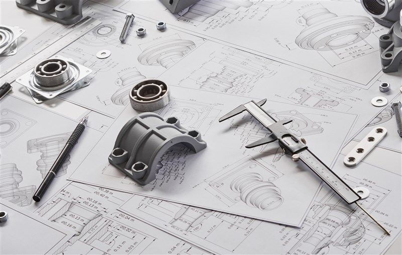
Elements that carry power transmission elements such as gear wheel, belt and pulley or chain wheel mechanisms are called shafts. Shafts that assume this carrying task are supported with journal bearings and ball bearings (rollers). Part of shafts that is enclosed by a bearing is called the journal. That’s why these are called journal bearings.
A journal bearing system consists of two main parts: a rolling journal and a fixed bearing block. The bearing may cover the journal partially or completely. The bearing can be called full bearing or partial bearing accordingly. There is a gap between bearing and journal diameters. This is called bearing clearance (c). Bearing clearance is used for assembling the shaft and bearing, creates the gap needed for the lubricant, helps decrease thermal expansion, and helps minimize the axial misalignment and/or deflection problems.
Nominal dimensions of bearing and journal are the same; but the necessary cavitation for oil film is created between bearing surface and journal surface by selecting appropriate tolerances in design and production. If we take bearing diameter as D and journal diameter as d, the formula to calculate bearing clearance is c = D-d. The bearing clearance to journal radius ratio is called relative bearing clearance. It is usually shown as y in bearing design, and it is calculated as y = (D-d)/d. Relative bearing clearance (y) depends on various factors such as the load on the bearing, speed of the shaft, dimensions and tolerances. It should be underlined that performance of the bearing to be designed will be greatly affected by any change in this number.
As the bearing clearance will vary between the highest and lowest limit values according to the dimension tolerances of the bearing and the shaft, average bearing clearance and average relative bearing clearance values are considered in bearing design calculations. However, for safety, minimum and/or maximum bearing clearances should also be checked by taking into consideration the surface roughness values.
As a general design criterion, lower y value is selected at low shaft speeds and high bearing loads, while higher y value is used at high shaft speeds and low bearing loads. When bearing clearance is high, the pressure in bearing increases and the pressure distribution curve tapers at the center of the bearing. In practice, it is generally accepted that the bearing clearance between shaft (journal) and bearing should be around 1‰ of the shaft diameter. If we take y≥0.002 under operating conditions with high shaft speed and low bearing load, friction is decreased and there is less temperature increase in bearing. According to the shaft speed, the y = 0.8 10-3 (U)1/4 formula is recommended for average relative bearing clearance. In the formula, speed is peripheral speed in terms of [m/s]. It should be underlined that the bearing temperature in real operating conditions will be much higher than in production conditions, and the bearing clearance may change due to the wear on journal and bearing surfaces as a result of operation over time. (to be continued)
(References: Babalık, F.C., Çavdar K., Makina Elemanları ve Konstrüksiyon Örnekleri, 8th Edition, Dora Printing-Publishing and Distribution Ltd. Co., Tevrüz, T., Makine Elemanları ve Konstrüksiyon Örnekleri, Vol. 2., Çağlayan Bookstore, Gemalmayan, N., https://websitem.gazi.edu.tr/site/nihatgem/files, Kurbanoğlu, C., Makina Elemanları, Teori, Konstrüksiyon ve Problemler, Nobel Printing House, Durak, E., Industrial Lubrication Techniques Lecture Notes)


