


Prof. Dr. Ertuğrul Durak
Dept. of Mech. Engineering, Suleyman Demirel University
ertugruldurak@sdu.edu.tr
The project titled “Smart Viscosity Measurement and Control System” (Project No. 1919B012431971), funded under the TÜBİTAK BİDEB 2209-A University Students Research Projects Support Program and conducted within the scope of the Graduation Project I-II course that I supervise, has been successfully completed. Implemented by project coordinator Rashad Rahimzade and researchers İsmail Erdoğan, Abbas Emirhan Mert, Kadir Çelik, and Ali Mutlu, the project stands as a valuable example of the potential that engineering students can demonstrate when provided with appropriate opportunities and support. I congratulate the project team and wish them success in their academic and professional careers. This article has been prepared to share the outcomes of the project with readers.
Viscosity is briefly defined as the internal resistance of a fluid to flow. It is a critical parameter in tribology and engineering design. Devices used to measure the viscosity of fluids are known as viscometers. Accurate viscosity measurement is an important engineering criterion for maintaining quality standards and system performance in industrial processes. Traditional manual viscometers are susceptible to user-induced errors during measurement, such as visual observation inaccuracies and timing errors. In addition, the high cost of measurement equipment and limitations in adapting to different operating conditions may create challenges in research and development activities.
Numerous types of viscometers are available. Dynamic and kinematic viscosity are commonly used to characterize fluid properties. For Newtonian fluids, whose viscosity changes linearly with shear rate, viscometers based on measuring the fall time of a spherical ball are widely used in practice. In conventional falling-ball viscometers, the ball’s transit time between two reference marks on the instrument is determined visually, while the elapsed time is measured using a stopwatch. The viscosity of the test fluid is then calculated using empirical equations based on the geometric and material properties of the selected spherical ball. In this method, both the determination of the ball’s position and the operation of the stopwatch depend largely on the user’s performance. To eliminate these drawbacks, the project involved conceptual design, detailed design, manufacturing, assembly, and validation testing of a prototype equipped with precision sensors and software support.
The mechanical design of the system was developed to provide measurement conditions consistent with the most accurate approaches reported in the literature (Figure 1). The measuring chamber incorporates a glass cylinder operating at a fixed 20° angle in accordance with the Höppler principle. This inclination prevents free fall of the spherical ball and ensures controlled movement along the inner wall of the tube, thereby improving measurement accuracy. To enable measurements at different temperatures, the sample tube is housed within a larger transparent Borosilicate 3.3 thermal-fluid chamber containing water and heating elements (two 400 W heaters, an SSR-25DA solid-state relay, and a DS18B20 temperature sensor). Custom-designed upper and lower covers produced through additive manufacturing, together with O-rings and liquid gaskets, ensure leak-proof operation. A stepper motor and automation unit provide both the rotational movement required to achieve thermal equilibrium and the precise 20° measuring position. A rubber-mounted coupling was selected to damp vibrations from the drive motor, while the supporting shaft is stabilized using two pillow block bearings.
The electronic infrastructure is based on a distributed microcontroller architecture capable of simultaneously handling viscosity calculations and precise rotational control. In this configuration, an Arduino Mega 2560 processes sensor data and performs viscosity calculations, while an Arduino Nano controls motor movements based on commands received from the main controller. A three-stage strategy was employed to isolate electromagnetic interference. First, capacitors and ferrite-core filters installed on motor and heater lines absorb switching-induced voltage fluctuations and preserve signal integrity. Second, sensitive sensor and display cables are shielded. Finally, the software temporarily ignores sensor inputs during periods when the heater generates the highest levels of interference.
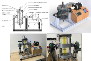
Figure 1. Main components of the smart viscosity measurement and control system
In summary, a fully autonomous Smart Viscosity Measurement and Control System was successfully designed and calibrated within the scope of the project (Figures 2 and 3). The system eliminates observation errors, thermal fluctuations, and manual mixing difficulties associated with conventional Höppler viscometers.
Thanks to its dual-microcontroller architecture, hardware-based RC filtering, and sensor shielding, electromagnetic interference does not compromise measurement accuracy. Mechanical stability is ensured through an aluminum sigma-profile frame. Position-control functions based on the MPU-6050 sensor and an autonomous “Mixing Mode” algorithm improve ease of use while minimizing the risk of incorrect measurements.
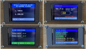
Figure 2. Sample measurement screens
The accuracy of the system was verified through thermal tests conducted with ISO VG 46 reference oil, using Stokes’ Law and Ladenburg wall-effect corrections. The overall instrument constant (K-constant) was successfully determined and integrated into the software, enabling viscosity calculations in accordance with ASTM D341 standards.
As a result, with its robust hardware architecture, intelligent software algorithms, and validated measurement accuracy, the system has the potential to accelerate laboratory and quality-control processes. It is considered an innovative, locally developed R&D testing device that contributes both to the scientific literature and to industry.
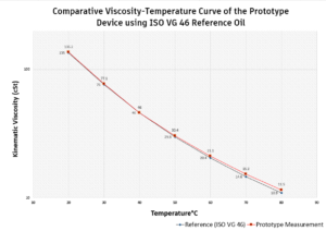
Figure 3. Comparison of ISO VG 46 reference oil and prototype measurement results (ASTM D341)
Reference: Project No. 1919B012431971, Smart Viscosity Measurement and Control System, Project Coordinator: Rashad Rahimzade, Final Project Report, 2026.
Acknowledgement: This work was financially supported by the TÜBİTAK 2209-A University Students Research Projects Support Program (Project No. 1919B012431971, “Smart Viscosity Measurement and Control System”). The authors gratefully acknowledge TÜBİTAK for its valuable contribution to the development of applied R&D culture at the university level and the realization of innovative engineering ideas.
#SmartViscosityMeasurement
#ViscosityMeasurement
#Tribology
#ResearchAndDevelopment
#EngineeringEducation